

Happy Holidays and Happy New Year From the Adiona Team!
- alexander.davis
- Jan 11, 2022
- 5 min read
Updated: Jan 12, 2022
Good Morning Everyone!
My name is Alex, I'm the resident mechanical engineer over here on the Adiona team.
At the beginning of winter break we were fortunate enough to get a few gifts to start playing with so we can start building and bringing Adiona to life. They're a little rough around the edges but if there's something us engineers love its restoring, renovating, and reusing old parts. It saves money and it's good for the environment so why not?
The Motors
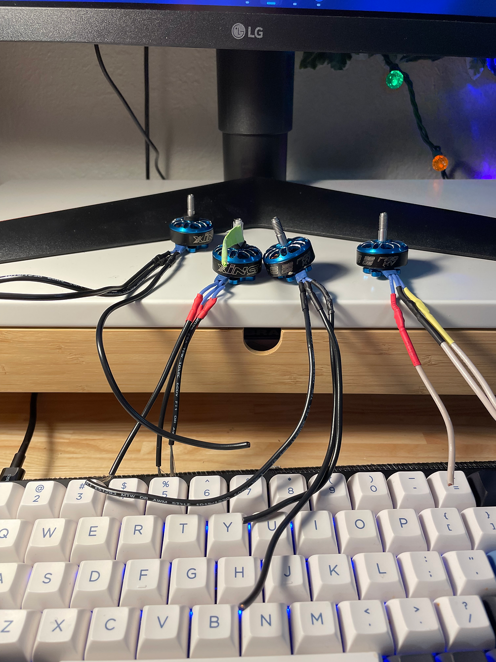
The first present in our bag of used parts is a set of 4 brushless motors.
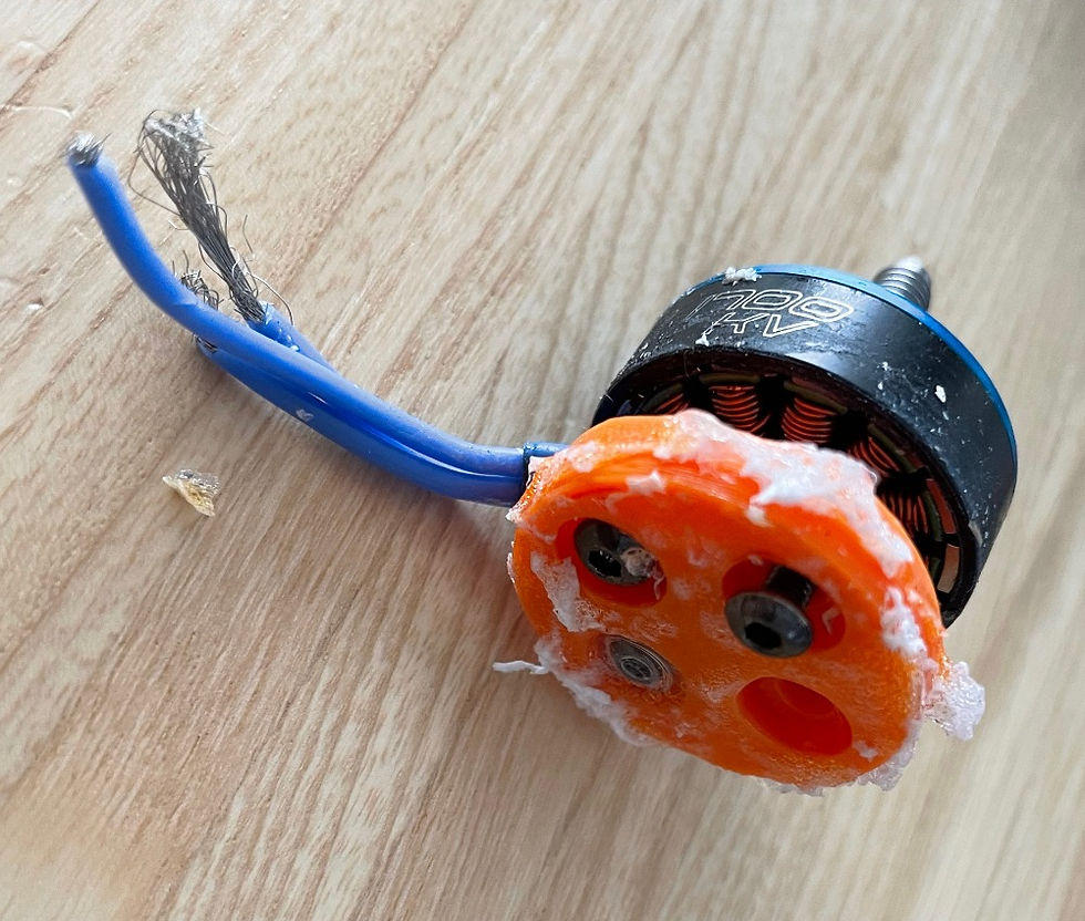
They are XING-E 2206 1700 kV brushless motors meaning they have a width/diameter of 22 millimeters and shaft length of 6 millimeters, the motors we chose for our final design are 2207 motors with a similar kV rating so these should work perfectly for now!
It's quite obvious right off the bat that these motors are fresh off of an old project and need a little help to get ready for our mission.
There's slight damage to the lead wires on all four motors but much more notably it seems like the previous teams custom motor mounts were left on. I suspect that this is because the mounting screws might be held in place by the leftover acrylic we see coating the bottom of the part.
I was actually really excited when I saw this because it meant I got to put on my Sherlock Holmes hat and see what I could learn about the motor's previous team and their project.
[WARNING RAPMANT SPECULATION AHEAD - PROCEED WITH CAUTION]
The bottom of the 3D printed part seems quite smooth due to the acrylic layer and it's even difficult at times to see the layer lines aside from a few artifacts where it looks like there was a little bit of under-extrusion meaning the 3D printer nozzle didn't deposit enough plastic in the area it was supposed to. If you didn't show me the side view of the part where the layer lines are more prevalent I might have thought this part was injection molded!
I'm willing to bet that these mounts are printed out of an ABS plastic filament. There seems to be slight warping on a few of the edges of the bases. While this can happen with most kinds of thermoplastic filaments, it's incredibly common with ABS filament and is even quite difficult to avoid. If the team decided to print these mounts out of ABS there must have been a good reason for it. Though ABS is quite a common 3D printing filament, it's quite difficult to print due to its natural heat resistance (the same reason that it warps so easily during cooling), not to mention it's actually weaker than the easier-to-print PLA and PETG alternatives, on top of all that it tends to release toxic fumes when you print it so it's dangerous to boot! It's likely that the mystery team anticipated that they would need ABS's heat resistant properties. My guess is that they were using these brushless motors in an outdoor quadcopter. Not only would these motor mounts have to resist the heat of the sun; during operation the coils in these motors would heat up quite a bit from internal resistances and the propellers would likely blow air right past the coils carrying the heat directly to the motor mounts below.
I believe the acrylic goo that's caked on the bottom of the mount was either used to weld the motor mount to the teams quadcopter frame or to just ensure that screws stay put during the flight since screws like this sometimes turn on their own with the vibrations of the motor.
The Disaster
The leads on two of our motors seem to have haphazard cuts throughout the length of the wire with bits of conductor and insulator hanging off everywhere. These cuts all seem like they were hit with the same angle of attack one after another leading me to think there was a tragic accident at the end of this project where these wires ended up caught in the path of the drone's propellers and were subsequently cut to pieces, sadly destroying the drone.
The Restoration
It seems like these motors have had a pretty tragic past, let's give them some redemption!
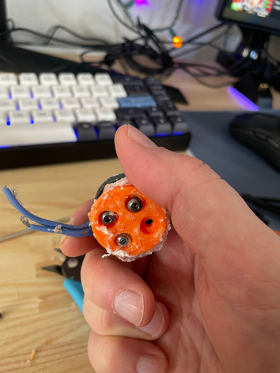
First, I carefully scraped away the acrylic holding the remaining screws in place on each motor base so I remove them and subsequently the bases.
The screws used are metric M3x8 hex screws. Meaning that the width/diameter of the threaded part of the screw is 3mm and the length of the threaded part (called the nominal length) is 8mm. We may find it easier later to use the imperial equivalent screw information especially when we start machining so I'll leave that here as a reference as well:
Imperial Equivalent Nominal Size No. ---> #4
Imperial Recommended Drill Bit Size ---> 1/8 in.
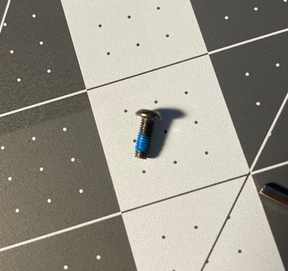
Something to note about these screws is the blue coating seen here at the end of the screw. This is called thread-locking fluid and it's used for exactly what it sounds like it is. It keeps the screw locked in place during vibrations and shock. It's color coded for strength and permanence. Thankfully the team that was using these motors just used blue medium strength thread-locking fluid.
This combined with that acrylic seal means those screws were extremely secure and that it's extremely understandable no one tried to remove them before giving the motors to us.
After removing all of the motor mounts and cleaning off any stuck on acrylic it's time to turn our attention to the wires.
The two motors with the frayed wires were easy enough to work with. After cutting off the damaged ends there was more than enough of the leads left for me to splice new wires onto.
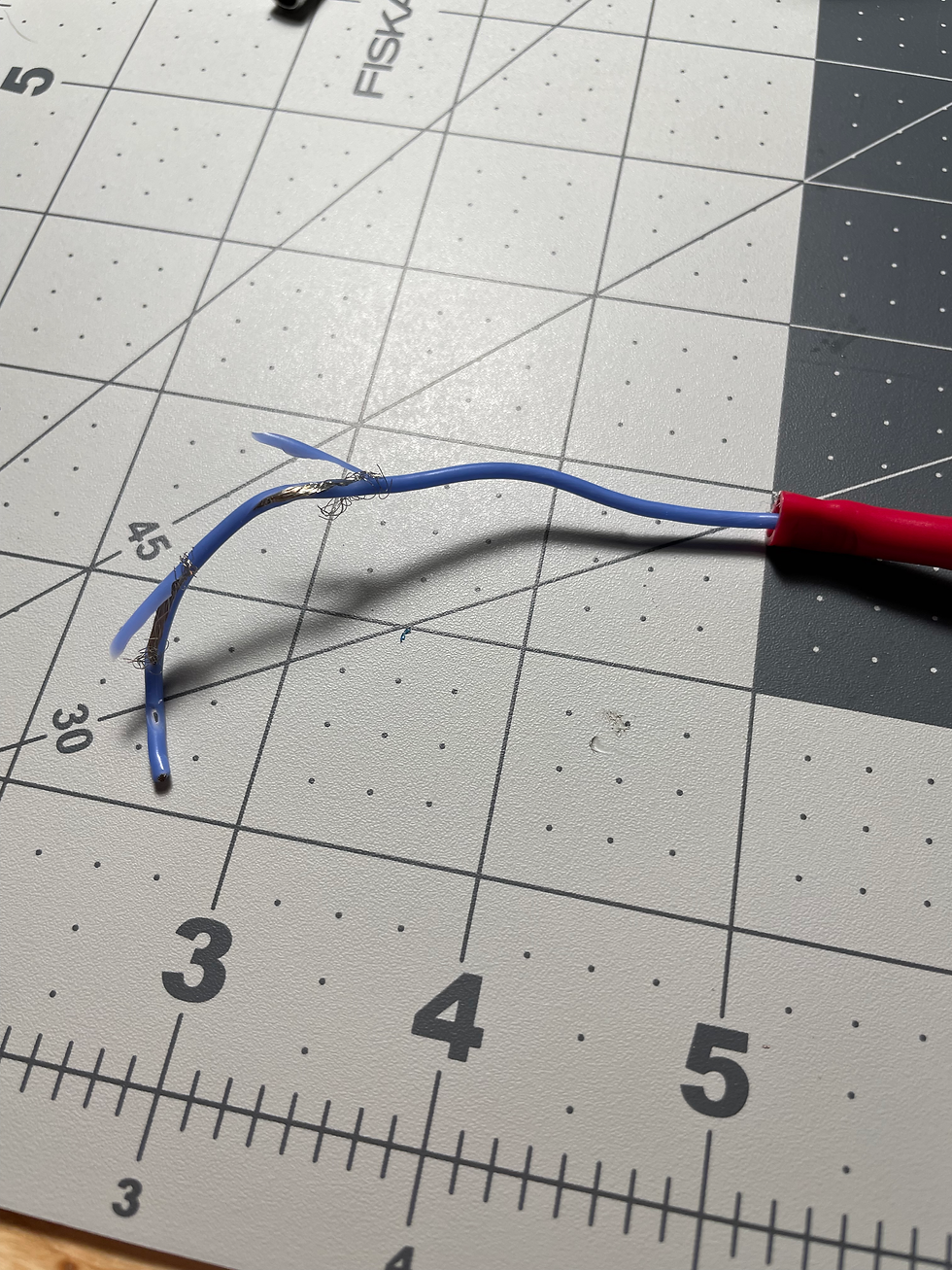
In come our two problem children:


These motors have extremely short leads which makes splicing more difficult and much more stressful. After some careful contemplation and some even more careful procrastination, I stuck the motors in some helping hands and knocked out the last six splices.
Here's a family photo of the bunch with their brand new leads and their new heat shrinks to keep their joints safe. I almost feel like I should name them after all of this.
Battery and ESCs
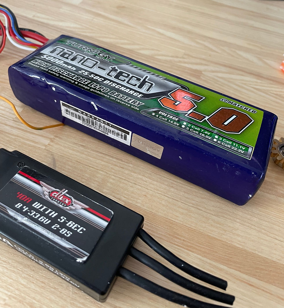
Luckily, the ESCs and battery are in pretty good shape! The battery still has its native leads and connectors and the leads on all four controllers are more than long enough for prototyping so we'll leave all of these as is for now and get to testing all of the components
Testing the Motors and ESCs
Now for the moment of truth....
"ITS ALIVEEEEE"
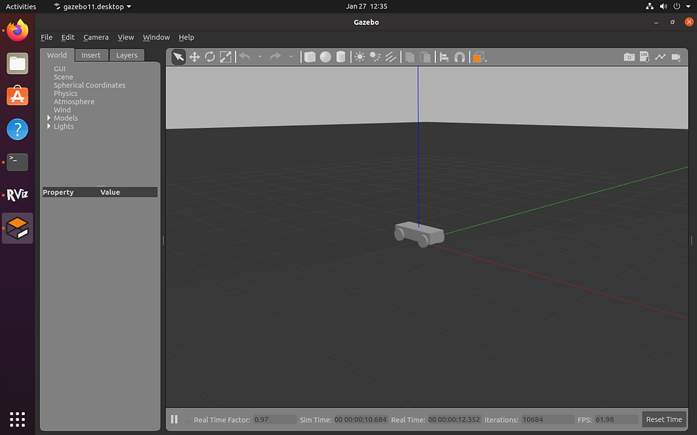
Now before I get to modeling these components and incorporating them into our CAD design there is one last thing I need to do.
Some Raspberry Pi for My Teammates
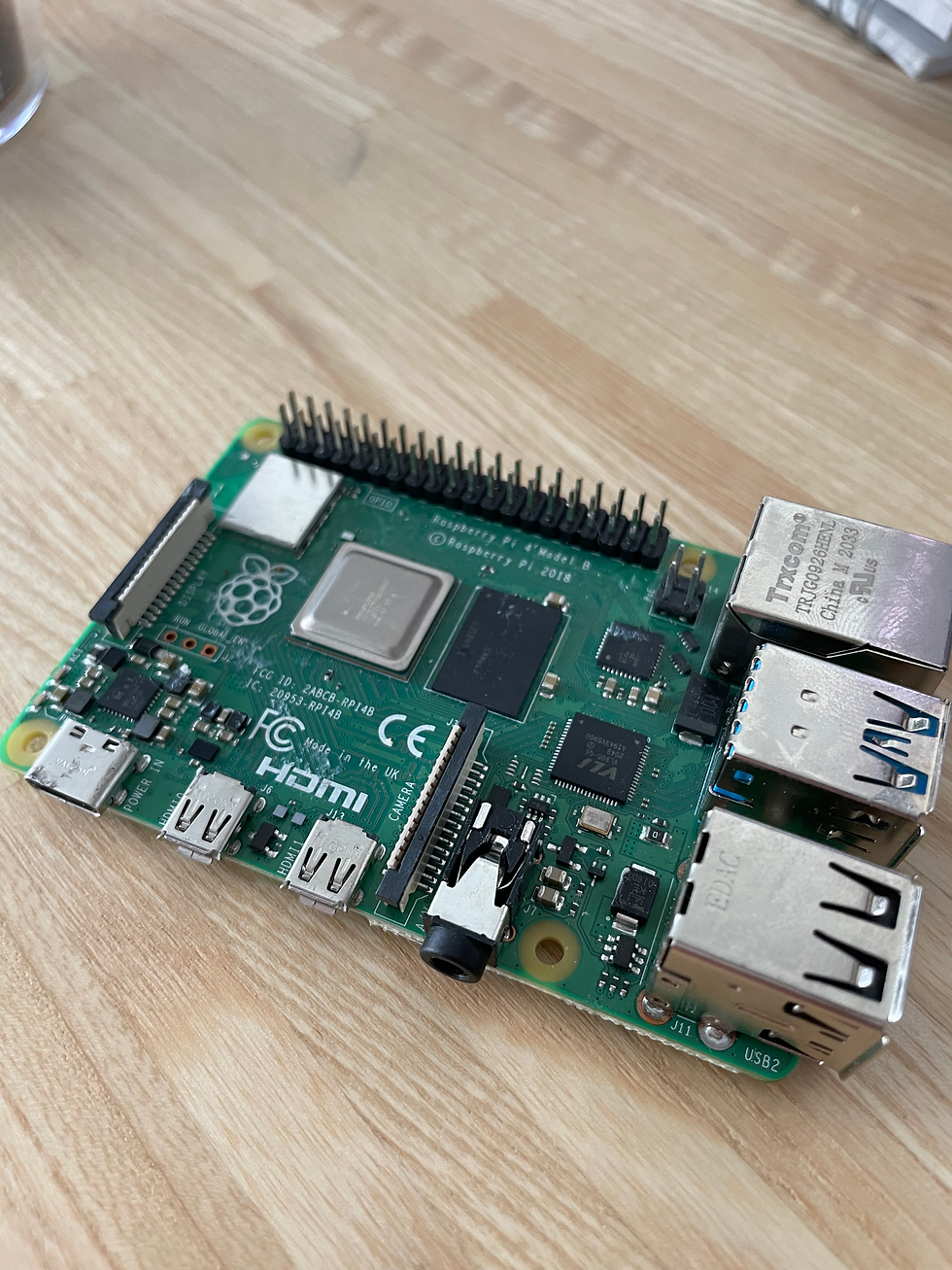
This is the last gift we got from the used parts shop during winter break. It's a Raspberry Pi 4 Model B. Everything seems to be in working order but the board is quite dirty. So before I hand it off to our computer scientists I'm going to give it a quick bath and remove all of the caked on mystery materials.
Using some cotton swabs and some isopropyl alcohol, I gently cleaned the PCB, ports pins and surface mount components.
Here's a quick montage I made of that process!
Goodbyes and Going Forwards
We hope you all had a wonderful break and that you'll tune in next week for my second blog post where I'll be posting the CAD work I do this week and talk about manufacturing the MK I of our rover! Keep your eyes peeled as well for my teammates blogposts - especially if you're interested in the computer science or electrical side of this project.
Good Night!

Comments